Sunday, April 26, 2009
Tank driving around in REDC 140!
The tank is currently responsive and driving around on the floor in our lab with wireless commands from the user. Test runs are recorded and will be up on YouTube soon. During these trials the responsiveness is being calibrated for the optimal turn and speed change, that is, remove any jerkiness during transitions.
Problems that occurred during fully operational tank control includes:
Problems that occurred during fully operational tank control includes:
- The H-bridges require at least 12 V to operate; our battery only supplied 9.6 V, so we replaced this power supply with a 21.6 V 1200 mAH cordless drill battery. This new battery was found at Big Lots for $20 with a free drill.
- Noise from the motors disrupted the control signals. Filter capacitors were placed on all of the power rails to reduce this AC noise.
- The pulse width modulated waveforms and direction signals from the MCU are passed through a restoring buffer. The waveforms are sent through two inverters, and the direction signals are inverted; this allows for a single hex inverter (74LS04) to accommodate all of these signals.
- A TX wire from the user's MCU and the XBee was severed, disabling communication.
Friday, April 24, 2009
Updates on the project
We have been working, so much however, that this development blog has not been updated for days!
Milestone II was completed this past Tuesday and can be accessed here.
This includes
Milestone II was completed this past Tuesday and can be accessed here.
This includes
- Wireless communication between the User and Tank
- Operating motors based on accelerometer input
- National Semiconductor LMD18200 3A, 55V H-Bridges, to drive the motors (the old stacked H-bridges finally died on us)
Tuesday, April 14, 2009
Milestone I
The goals for milestone I are complete by the deadline.
There is a minor problem with the XBee outstanding that is to be addressed today. Specifically communicating PIC to PIC, this may be due to using the incorrect sending and recieving function (``printf'' may be too fast, perhaps send character by character with a specified delay).
The milestone I report can be downloaded here.
First stage in motor control
This video demonstrats the ultrasonic sensor controling the speed of the motors. If an object is within one foot, the motor stops. If the object is between 1 and 2 feet, the motor is at half power. Finally if the object is greater than 2 feet away the motors move at full power.
Monday, April 13, 2009
Accelerometer experimental values
 Table 1: Accelerometer Calibration Experiment Results
The following test was performed on the calibrated output of the accelerometer. Initially the accelerometer was calibrated in the static state sitting on a table; increments based on a degree measurement. The X and Z were measured as shown in Figure 1, and Y was measured as shown in Figure 2.
Calibration of the module is done by taking a snapshot of the x, y, and z values during startup. The values in Table 1 are simply the difference between these initial values and the sampled values at the various angles. That is
K_calibrated = K_initial - K_sample,
where K is either the x, y, or z direction.
Note:
This experiment is going to be refined to show the sampled value along with the calibrated value, where the rollover is shown. Updates to come...
Note:
This experiment is going to be refined to show the sampled value along with the calibrated value, where the rollover is shown. Updates to come...
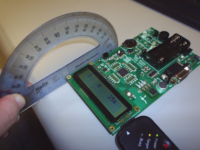 Figure 1: Measurement setup for X and Z axis
 Figure 2: Measurement setup for the Y axis
Friday, April 10, 2009
Accelerometer and motors functional
Today we accomplished both the accelerometer and motor control with an H-bridge.
The accelerometer was tested by writing an interrupt service routine (ISR) that samples eight values from each of the X, Y, and Z vector directions. This was to ensure that the sampling frequency was great enough and was not being slowed down by other programming tasks. After the total of 24 values were recorded into the X, Y, and Z arrays, a function is called from the ISR that disables interrupts (so that new values do not alter this test) and prints out the collected results on Hyper Terminal. Once all of the values are printed, interrupts are enabled so that this process continues indefinitely.
Motors operate independently with pulse width modulated waveforms sent to the H-bridges. The regulated 5 V power was removed from the H-bridge so that the motors now revieve the full 9.6 V of power.
Subscribe to:
Posts (Atom)